System 80 Sound Module for Black Label Models
August 25, 2024 - Reading time: 7 minutes
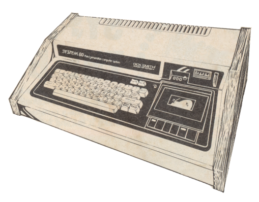 The Dick Smith System 80 was a clone of the TRS-80 Model 1 computer released in 1980. There were at least four revisions of the System 80 over the years, the last identified as the "Blue Label" model as it had a dark blue label rather than a black one. The Blue Label was the only one to be fitted with internal sound and speaker. This made it great for playing the many TRS-80 games that used the cassette port #1 for producing sound.
Here I will install a sound module that will add Blue Label sound to the earlier Black Label models. This module will also include a volume control which was not included in the Blue Label model. Audio output is muted when using the cassette for saving or loading.
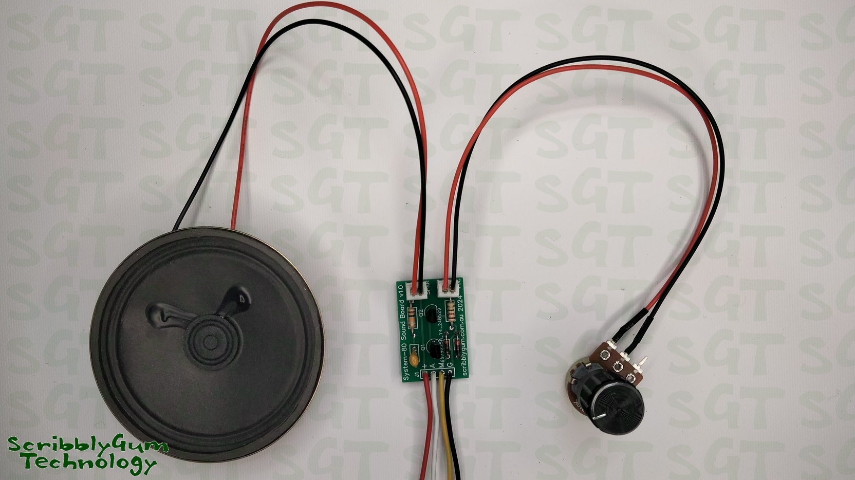
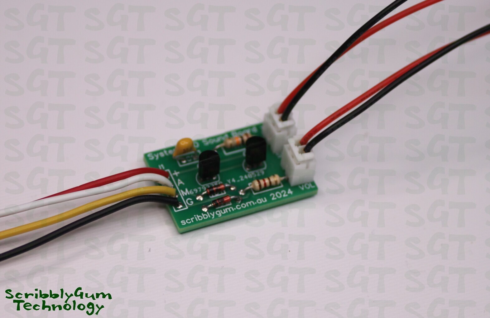 This is the sound module that I will be installing. It consists of a small PCB with four flyleads that need to be soldered to the video board. It also has plug in connections for the speaker and volume control. It is supplied as a kit (product link) with a populated PC board and the correct size speaker for the System 80 case and volume control.**
The first part of the installation involves installing the speaker, there is already a placeholder for the speaker in the bottom of the case. Open the case then remove the keyboard (you can unplug the connection at the keyboard). Try not to bend this connector too much, it tends to be fragile and can break especially where it connects to the mainboard. The same is true for the connector that connects the two PC boards together.
Once the keyboard is removed, disconnect the power and tape player connectors then remove the screws that hold the PC boards in place. Technically you really only need to remove the video board (right hand side), but you will also need to disconnect the two boards. Alternatively you can carefully lift both boards up carefully and remove them together keeping the connector in place. Use the method you feel comfortable with. You might also find it easier to work on with the cassette deck removed.
If you still have the RF video cable connected to the modulator, you'll need to be careful when removing the board as this cable is routed through the bottom of the case. I have already removed the RF cable from my machine as I only use the composite output these days via the back video port and the cable was just getting in the way.
![]()
Here is the System 80 case with the boards and cassette deck removed. You can now see where the speaker is meant to be installed. Seems like they always planned to include sound at some stage.
The holder has two posts that you can install speaker brackets into, at the time I didn't have any brackets so I just chose to hot glue the speaker in for now.
While here you can also install the volume control. I've installed it here on the right hand side of the case. If you don't want to drill a hole in your case (understandable) then you can just use a jumper block in the volume connector and not use the volume control at all.
![]()
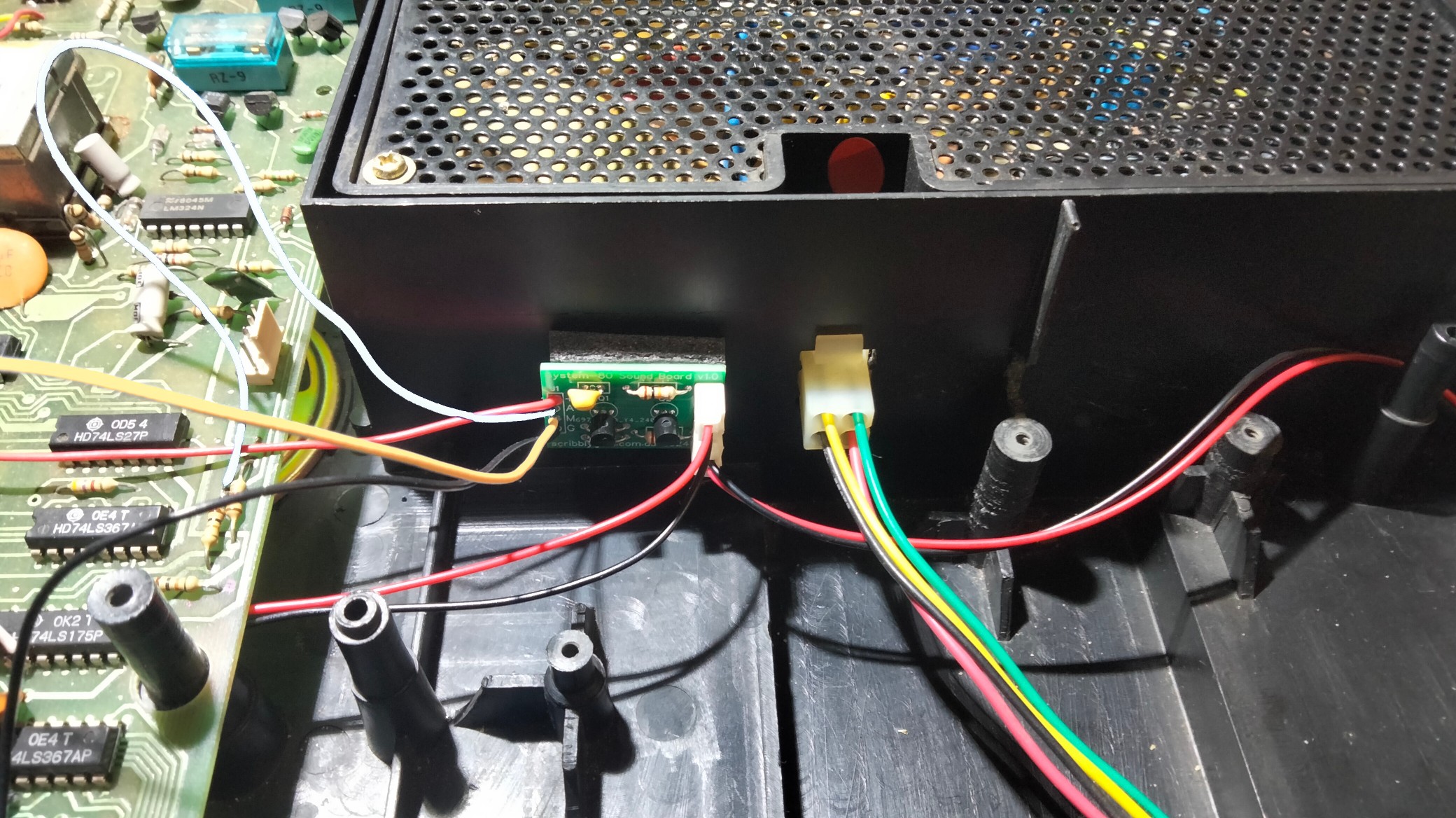
Here's the case with the speaker and volume control installed. Now the boards can be put back in place. Leave the keyboard and tape deck out for now. The four wires can now be soldered to their respective locations. The red wire connects to the power source (9V) which is easily found at the RF modulator. Solder it to the middle connectors (in this picture it joins onto the yellow wire at the modulator, but note the wire colours used on the modulator are inconsistent, just join it to the center connection where 9V should be present).
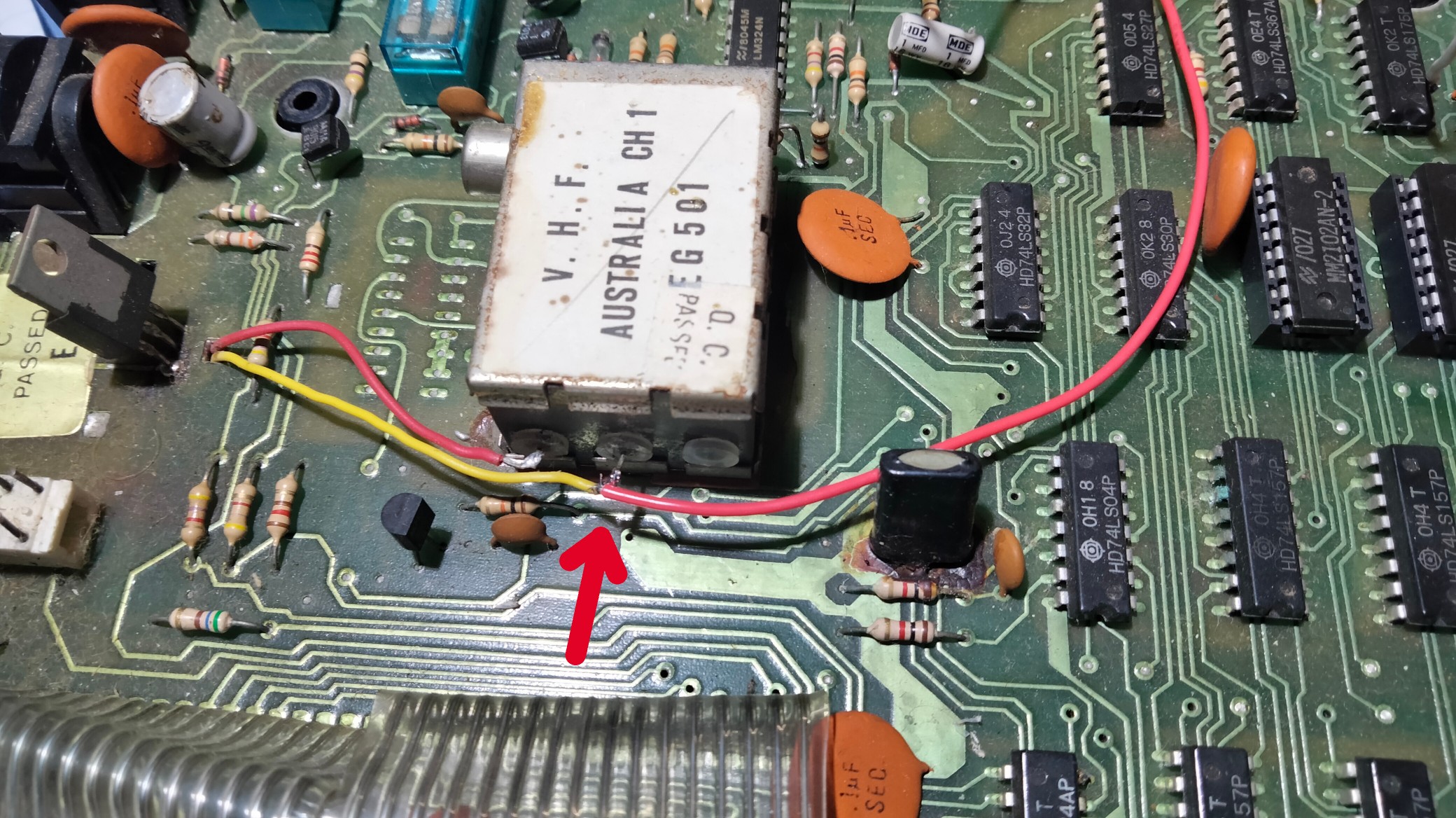
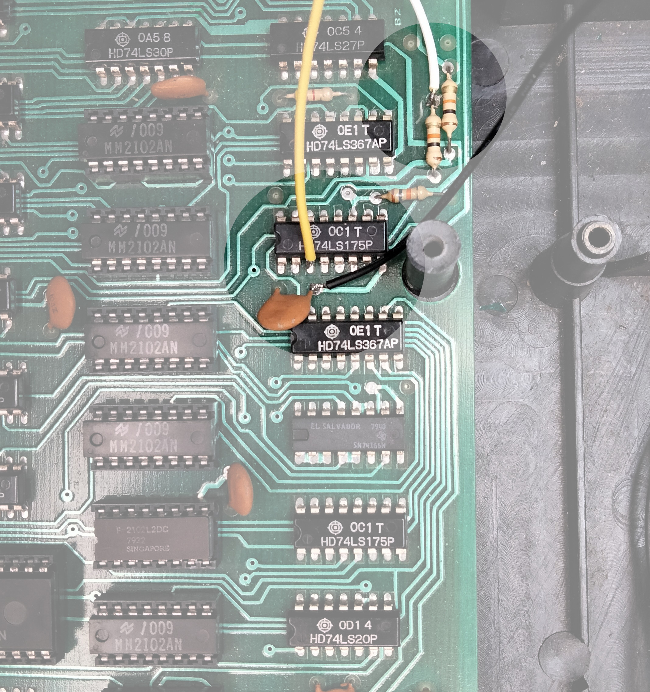
The white wire connects to the top of resistor R30 as shown below. The yellow connects to pin 3 of Z6. The black connects to ground, pictured it is connected to right hand side of Capacitor C8 (You could also connect to to Pin 8 of Z6 if you want but I tend to avoid soldering to IC's if possible).
Here is the installed module, you can attach it using double sided foam tape to a convenient location, make sure to avoid conflict with the cassette deck. Attaching it here to the outside of the power supply seems to work well.
And here is the result, for the test lets load up an old favourite, Robot Attack...