System 80 Lowercase Module for Black Label Models
August 31, 2024 Reading time: 6 minutes See Comments
 Lowercase was not standard on most of the Black Label System 80's as it was on the Blue Label. Although there were likely a few later model Black Labels that had lowercase. It's not always obvious that the machine has lowercase as it isn't active by default in Level II Basic. A lowercase driver program could be installed which would make the lowercase active. In the case of the Blue Label there was an in-built ROM routine to activate the lowercase characters.
The following short program will display the character set and also indicate if lowercase is installed:
100 CLS : FOR X = 0 TO 255 : POKE 15360+X,X : NEXT
200 PRINT@320,"LOWER CASE:";
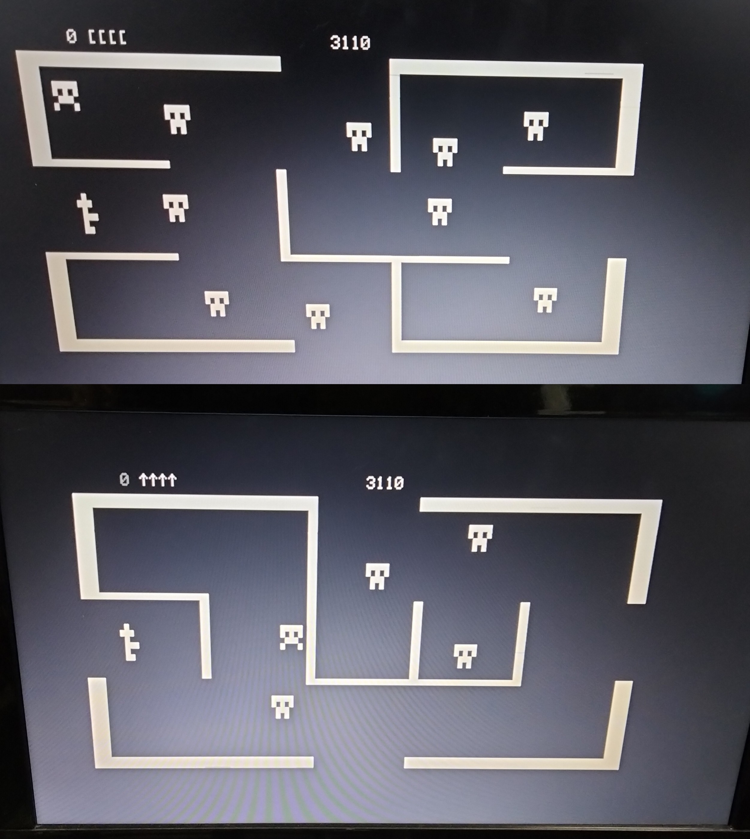
300 IF PEEK(15361)=1 THEN PRINT "YES" ELSE PRINT "NO"The result when no lowercase is installed:
This is with normal System 80 lowercase:
This is the modified set with arrows symbols instead of square brackets:
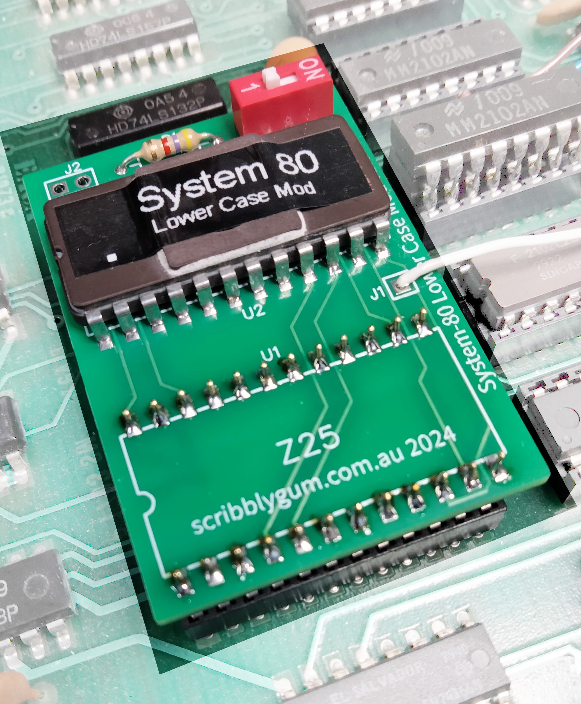
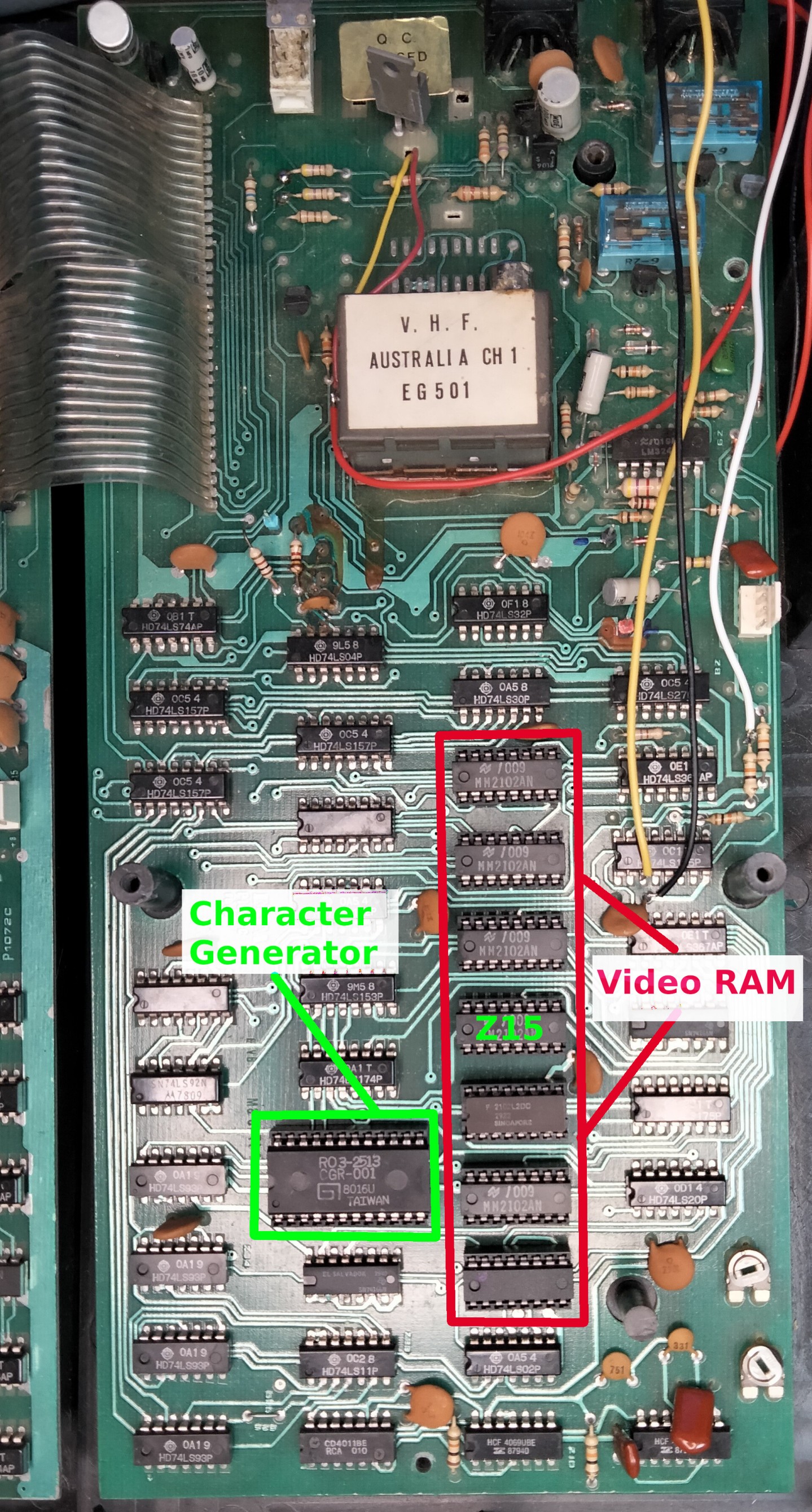
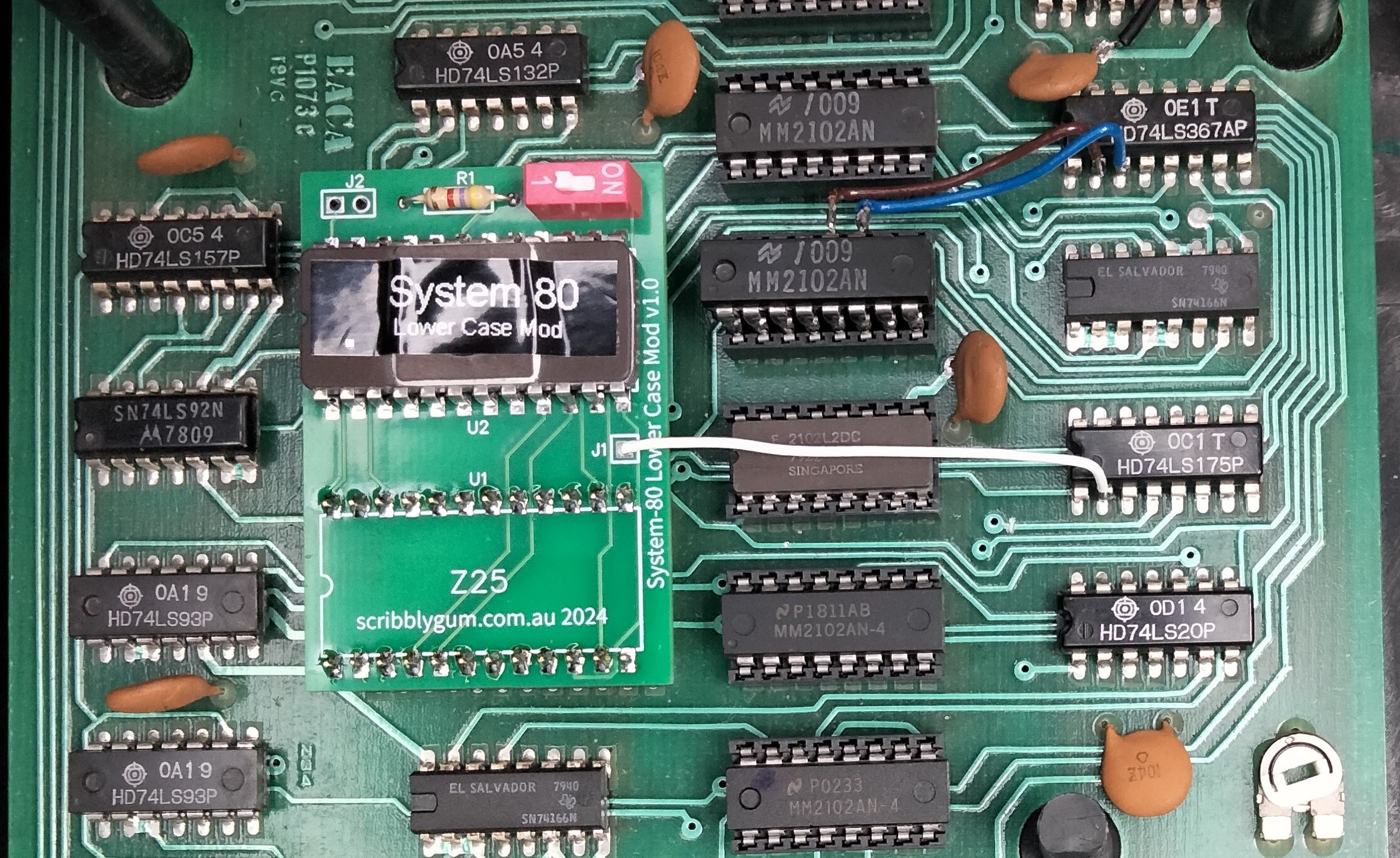
So if you've found that you don't have lowercase then consider installing this mod which will give you a choice of the standard System 80 lowercase or the modified set with the arrow symbols as found in the TRS-80 character set **. Below is an example of the early model video board. To cut costs only seven video RAM chips were installed, with only seven chips lower case is not possible, so the first thing to do is to add the eighth video RAM chip. We will do this by piggybacking the new chip onto an existing one.
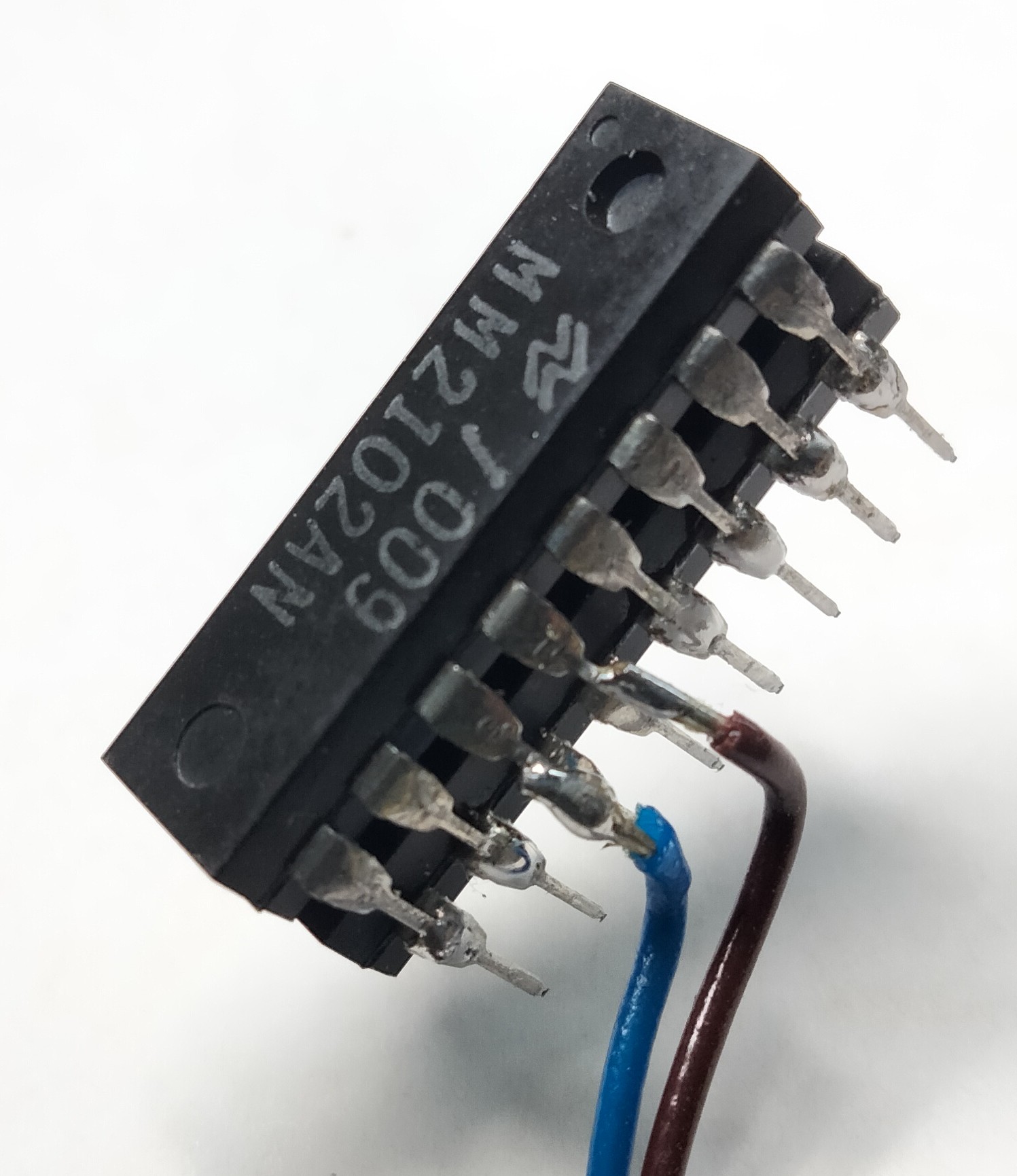
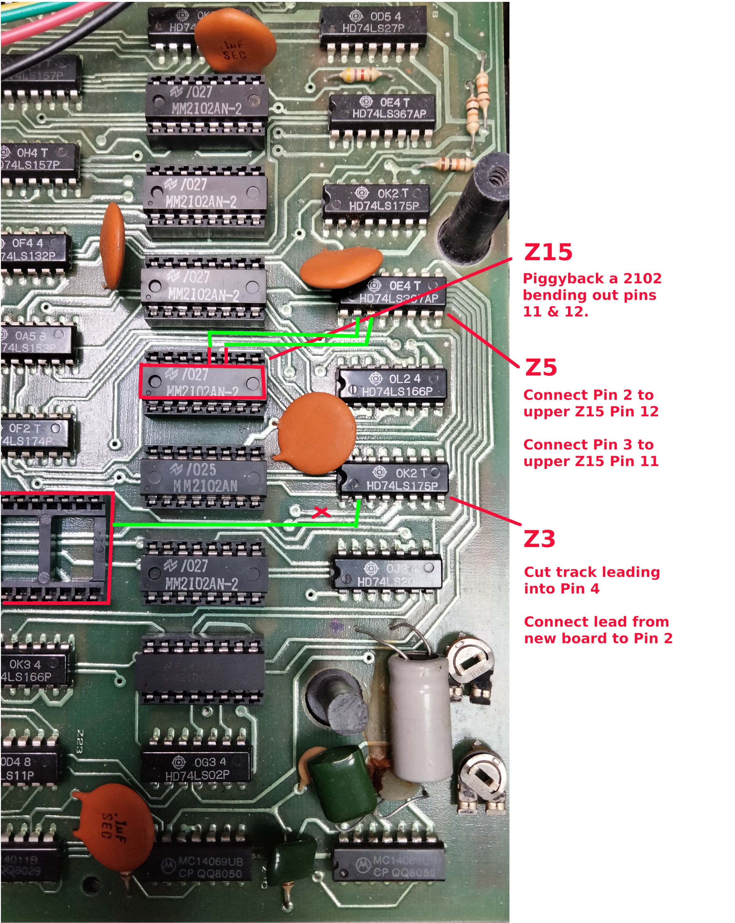
Remove Z15 (as marked on the above image) as this is the chip we will piggyback. Pins 11 & 12 of the top chip are bent out, all the rest of the pins are soldered to the lower chip. Once complete the pair can be inserted back into the socket.
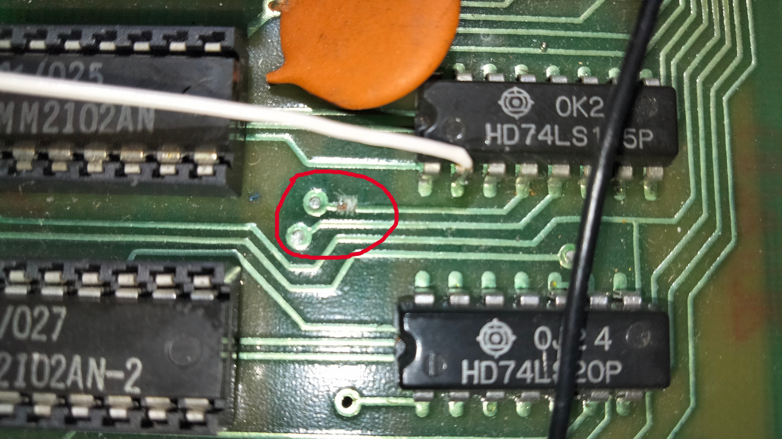
Now run a wire from the new RAM chip Pin 12 to Z5 Pin 2 and then Pin 11 to Z5 Pin 3. The last thing to do for the memory upgrade is to cut the track leading into Z3 Pin 4. See the picture below, the track needs to be cut where the Red X is marked. Best to check with a multi-meter that you've actually cut it successfully.
Now all that remains is to install the lowercase module, remove the character generator and place somewhere safe. At this point we need to talk about the socket. In another cost cutting exercise it is likely you have a "single wipe" socket installed (as seen in these pictures). These are the cheapest sockets available as they only have contacts that connect to the IC on one side of the pin. Much better are "dual wipe" sockets that connect either side of the IC pin and then there are machined pin sockets which contact to at least four points.
If using the single wipe socket the lowercase module may feel a little loose. If it is tight enough the lowercase will work fine but may dislodge too easily, a small amount of hot glue should help this. If the socket is very loose the only real way to fix it properly it to replace the socket (we won't deal with that here). Alternatively you could gently tease out the pins ever so slightly so they make a better contact.
Line up the module carefully with the pins and install it into the socket. The last thing to be done is to solder the flylead from the module to Z3 Pin 2 (as pictured above and below).
That's it all done, you can now run the little program at the beginning of this article and see your new lowercase characters. If you're careful you can even flip the little switch in real time and see the brackets change to arrows.
Spot the difference...
** You should only attempt this modification if you are confident with disassembly and soldering, if not you should probably find someone who has these skills to do it for you. We can't be held responsible if bad things happen. As with any vintage computer things can and will go wrong.
See Comments
System 80 Sound Module for Black Label Models
August 25, 2024 Reading time: 7 minutes See Comments
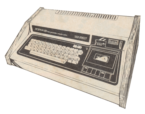 The Dick Smith System 80 was a clone of the TRS-80 Model 1 computer released in 1980. There were at least four revisions of the System 80 over the years, the last identified as the "Blue Label" model as it had a dark blue label rather than a black one. The Blue Label was the only one to be fitted with internal sound and speaker. This made it great for playing the many TRS-80 games that used the cassette port #1 for producing sound.
Here I will install a sound module that will add Blue Label sound to the earlier Black Label models. This module will also include a volume control which was not included in the Blue Label model. Audio output is muted when using the cassette for saving or loading.
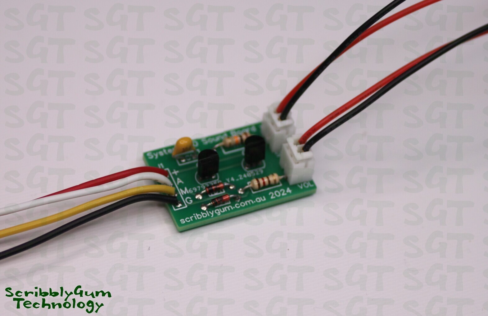 This is the sound module that I will be installing. It consists of a small PCB with four flyleads that need to be soldered to the video board. It also has plug in connections for the speaker and volume control. It is supplied as a kit (product link) with a populated PC board and the correct size speaker for the System 80 case and volume control.**
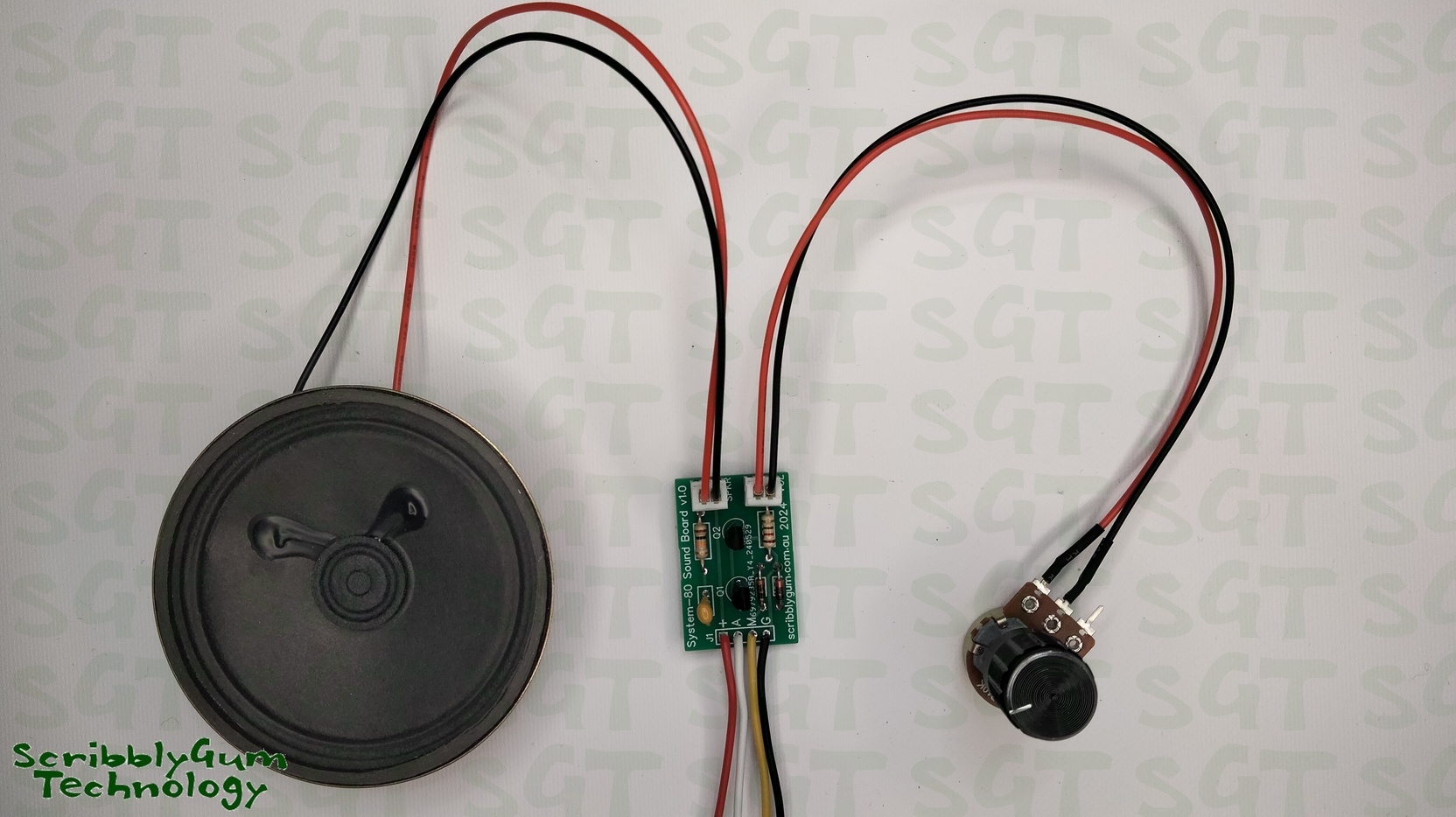
The first part of the installation involves installing the speaker, there is already a placeholder for the speaker in the bottom of the case. Open the case then remove the keyboard (you can unplug the connection at the keyboard). Try not to bend this connector too much, it tends to be fragile and can break especially where it connects to the mainboard. The same is true for the connector that connects the two PC boards together.
Once the keyboard is removed, disconnect the power and tape player connectors then remove the screws that hold the PC boards in place. Technically you really only need to remove the video board (right hand side), but you will also need to disconnect the two boards. Alternatively you can carefully lift both boards up carefully and remove them together keeping the connector in place. Use the method you feel comfortable with. You might also find it easier to work on with the cassette deck removed.
If you still have the RF video cable connected to the modulator, you'll need to be careful when removing the board as this cable is routed through the bottom of the case. I have already removed the RF cable from my machine as I only use the composite output these days via the back video port and the cable was just getting in the way.
![]()
Here is the System 80 case with the boards and cassette deck removed. You can now see where the speaker is meant to be installed. Seems like they always planned to include sound at some stage.
The holder has two posts that you can install speaker brackets into, at the time I didn't have any brackets so I just chose to hot glue the speaker in for now.
While here you can also install the volume control. I've installed it here on the right hand side of the case. If you don't want to drill a hole in your case (understandable) then you can just use a jumper block in the volume connector and not use the volume control at all.
![]()
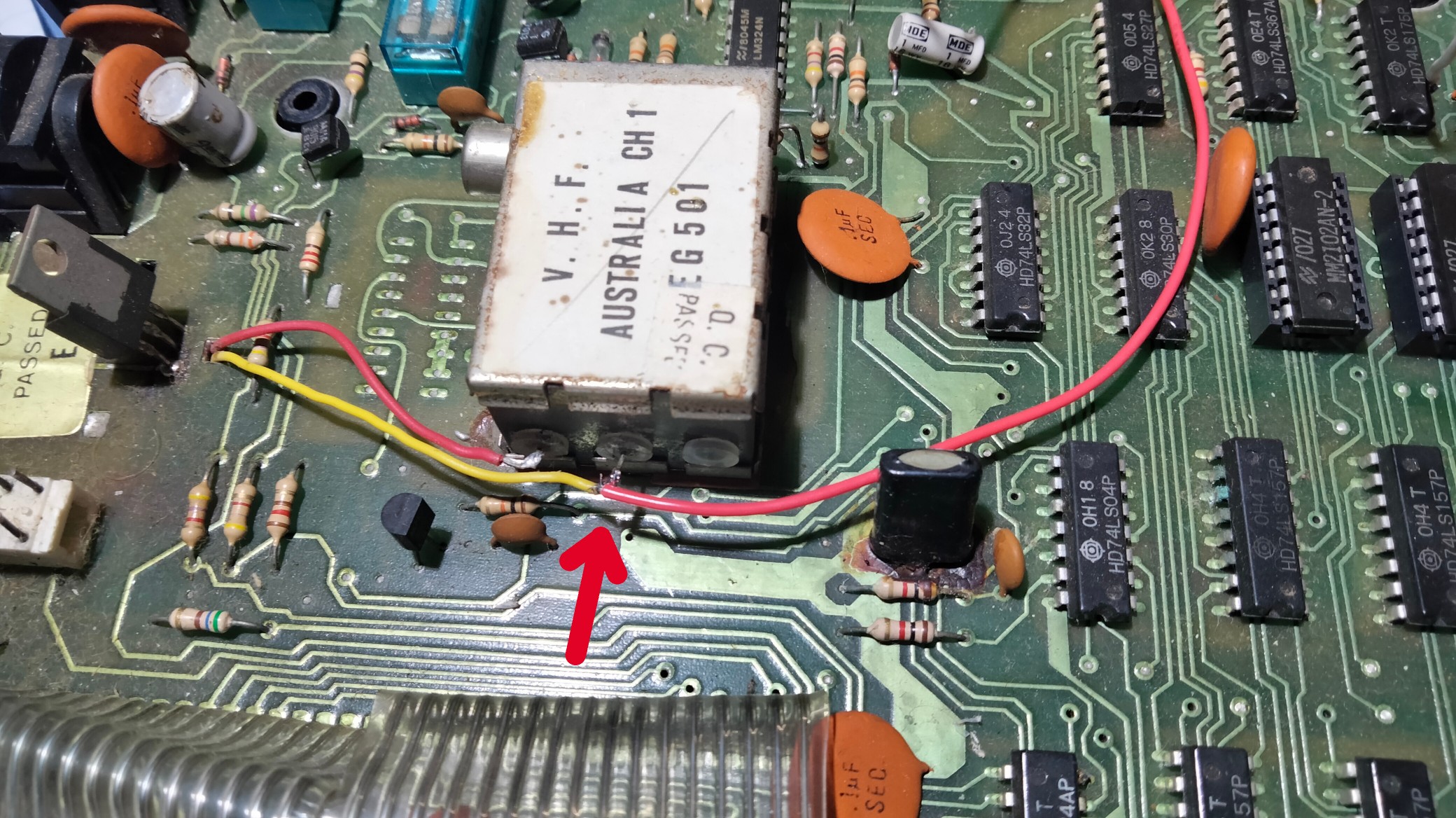
Here's the case with the speaker and volume control installed. Now the boards can be put back in place. Leave the keyboard and tape deck out for now. The four wires can now be soldered to their respective locations. The red wire connects to the power source (9V) which is easily found at the RF modulator. Solder it to the middle connectors (in this picture it joins onto the yellow wire at the modulator, but note the wire colours used on the modulator are inconsistent, just join it to the center connection where 9V should be present).
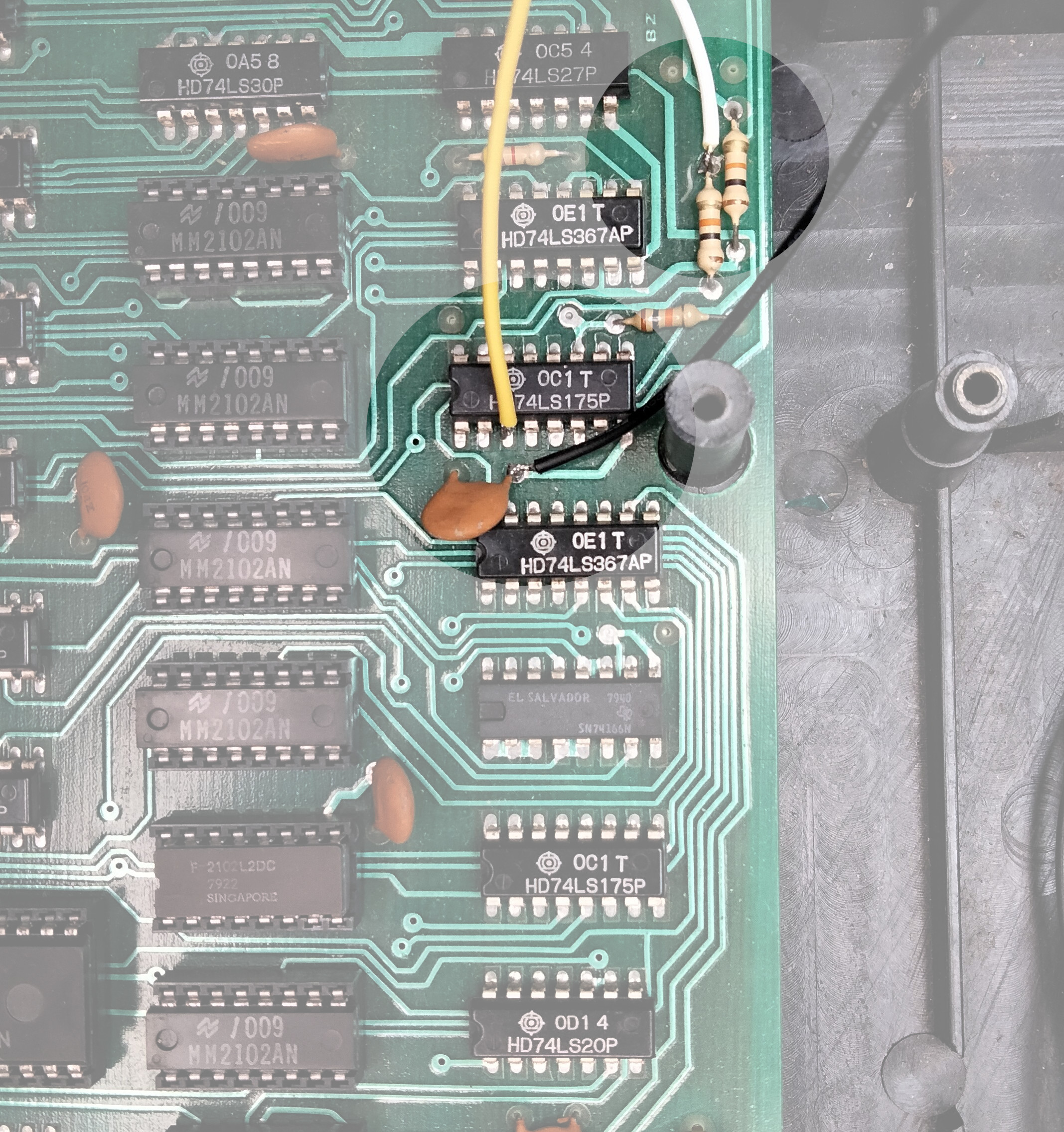
The white wire connects to the top of resistor R30 as shown below. The yellow connects to pin 3 of Z6. The black connects to ground, pictured it is connected to right hand side of Capacitor C8 (You could also connect to to Pin 8 of Z6 if you want but I tend to avoid soldering to IC's if possible).
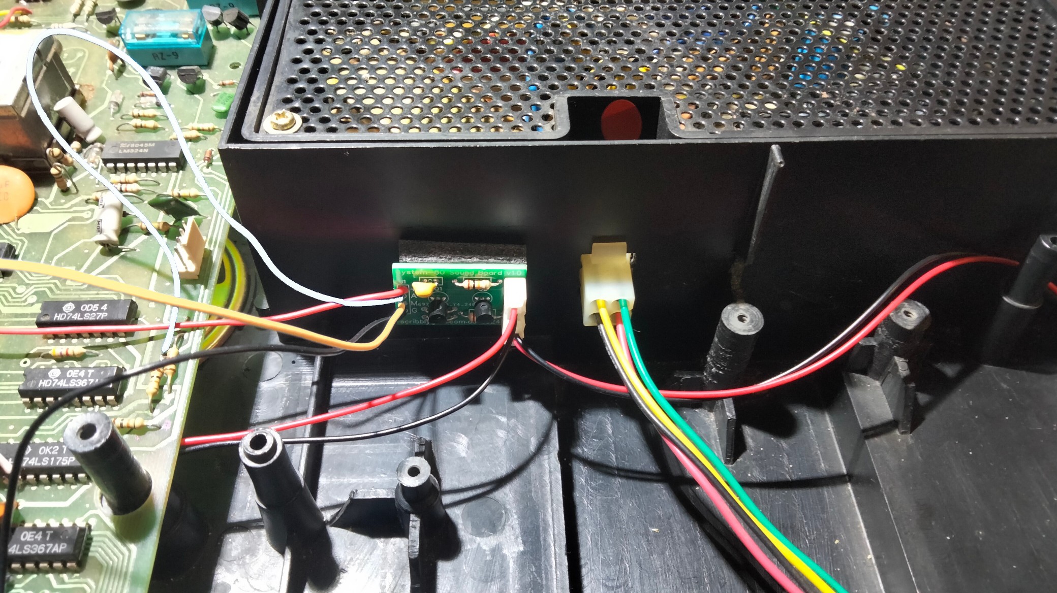
Here is the installed module, you can attach it using double sided foam tape to a convenient location, make sure to avoid conflict with the cassette deck. Attaching it here to the outside of the power supply seems to work well.
And here is the result, for the test lets load up an old favourite, Robot Attack...